PicoShock Devlog #2
These last couple of weeks I’ve kept my work on picoshock somewhat consistent, and I’ve also learnt a lot, really.
For starters, my first log entry was filled to the brim with mistakes, some pretty dumb ones, too:
- I didn’t even start the PIO program.
- I used
pio_sm_getinstead ofpio_sm_get_blocking: the difference between the two is that the second one waits for the RX FIFO to actually have some data to read. The first one, when the FIFO is empty, has undefined behavior. That explains the readings I was getting: the program didn’t even start and as such, the FIFO wasn’t getting filled. - The folks at the raspberry pi forum explained to me the nuances of clock frequencies in PIO programs: although it can be the case that I want a precise clock frequency matching that of the device I wish to interface (I’ll have to do this when implementing the console mode), it sometimes is not, and it’s better to actually set the frequency higher.
So the days I’ve been working on pico shock I’ve had a single goal: receive coherent data, as per the dualshock protocol. I’ve implemented the clock and acknowledge signals, too. So now, my PIO program looks like this:
.program dualshock
.side_set 1

wait 0 pin 2 side 1          ;; Wait for clock to go low, pull ACK high.
.wrap_target
wait_for_att:
  set x, 8 side 1            ;; Set bit counter: we want to read a byte.
  wait 0 pin 1 side 1        ;; Wait for ATT. PS2 wants to tell us something.

read_loop:
  wait 0 pin 2 side 1        ;; When clock drops from low to high,
  wait 1 pin 2 side 1        ;; read the values.
  in pins, 1 side 1          ;; Read the bit sent by the PS2.
  jmp x-- read_loop side 1   ;; Decrement bit counter.

acknowledge:
  push [15] side 1           ;; We've read a byte, wait for 12us before pulling ACK low.
  nop [14] side 1
  nop side 0 [5]             ;; Pull ACK low.
.wrap

% c-sdk {
  void dualshock_program_init(PIO pio, uint sm, uint offset, uint command_pin, uint data_pin, uint ack_pin) {
       pio_sm_config cfg = dualshock_program_get_default_config(offset);

       sm_config_set_in_pins(&cfg, command_pin);
       pio_sm_set_consecutive_pindirs(pio, sm, ack_pin, 1, false);
       sm_config_set_out_pins(&cfg, data_pin, 1);
       sm_config_set_sideset_pins(&cfg, ack_pin);
       sm_config_set_in_shift(&cfg, true, false, 8);
       sm_config_set_clkdiv_int_frac(&cfg, 50, 0);
       pio_gpio_init(pio, ack_pin);
       pio_sm_init(pio, sm, offset, &cfg);
  }
%}
It has grown quite a bit.
As per my understanding, sm_config_set_in_pins(&cfg, command_pin) sets both the pin and its 5 consecutive ones as input pins.
The pin you pass as an argument is called the base pin. As such, following the command pin I wired the clock and after that,
the attention pins. I could be wrong here, too, but, for example, to wait on a pin other than the command, you refer to
your pin with its bitmask. For example, 0b00000 is a 5 bit number. The first refers to the base, the second to the next one,
etc. But, I have my doubts on this: in wait instructions, for example, if you write wait 0 pin 0 you’re waiting for your
base pin to pull low… I think.
As the pin following the command one is the ATT pin, that’s my pin 1, and clock is my pin 2. So, I hope that:
wait 0 pin 2
Means that I’m waiting for my clock to pull low.
I’ve implemented ACK as a side set pin: it’s normally set high, but after reading a byte, I must wait 12us and then pull it low for (half, I’m still not sure how I will do that, meanwhile I’ll try for a full PS2 clock cycle) a clock cycle.
I’m also reading a single bit with every in instruction, as the playstation 2 pulls the clock low and then high and after that,
sends a bit.
Frequencies
If you’ve read my thread in the forum you probably know by now what I mean by me using the clock divider feature wrong. It wasn’t
actually because I wasn’t setting the frequency I intended to (500 KHz) but because in reality I want to set it higher. So:
sm_config_set_clkdiv_int_frac(&cfg, 250, 0) became sm_config_set_clkdiv_int_frac(&cfg, 50, 0). I’m now setting the PIO frequency
as, hopefully, 2.5 MHz. This means that nop side 0, the instruction that pulls ACK low, is wrong. As 2.5 MHz is 5 times faster
than 500 KHz, so, this instruction should be nop side 0 [5] instead. 5 cycles for us is a cycle for the PS2.
What has changed?
Well, now it seems I’m actually getting something out of the PS2, kind of. The printf sentence of my C program prints the number 800000 endlessly, which is off by 23 bits to the right (oh, yes, I want the ISR FIFO to shift to the right, I thought that LSB protocols shifted it to the left. Another one of the countless silly mistakes of my first post). The number I’m actually looking for is 1. Or 0x01 in hex notation.
What comes next
Well, now that I’ve set up the state machine’s frequency right, and receiving something that looks like relevant data, I now have to prove my hypothesis: should I shift everything I receive from the PS2 23 bits to the right to make sense of it? For this, I’ll implement the data (out) pin, send something, and see if the number the PS2 sends me as a response is different from 800000. If it is, I’ll shift that 23 bits to the right and see if it coincides with the protocol.
Until next time! This is the hard part: after this, it probably won’t be a walk in the park but I’m pretty certain the C portion of the library won’t be that hard to write.
Another update
Well, I was planning to post this on saturday, but I forgot, and when I had some free time to keep working on this, well, let’s say I’ve made some progress.
Updates to dualshock.pio
First, another fix to my pio program:
;; Before
wait_for_att:
  set x, 8 side 1            ;; Set bit counter: we want to read a byte.

;; After
  wait_for_att:
  set x, 7 side 1
It seems that me making stupid mistakes is a constant on this, oh well. Don’t be too harsh on me.
I also implemented the data bus in pio:
.program dualshock_data

.wrap_target
wait_for_output:
	jmp !osre wait_for_att   ;; Stall while we don't have data to output
	jmp wait_for_output

wait_for_att:
	set x, 7                 ;; Set bit counter: we want to send a byte.
	wait 0 pin 0             ;; Wait for ATT.

out_loop:
	wait 0 pin 1             ;; When clock drops from low to high,
	wait 1 pin 1             ;; send our data.
	out pins, 1              ;; Read the bit sent by the PS2.
	jmp x-- out_loop         ;; Decrement bit counter.
.wrap

% c-sdk {
  void dualshock_data_program_init(PIO pio, uint sm, uint offset, uint data_pin,
                                   uint att_pin) {
    pio_sm_config cfg = dualshock_data_program_get_default_config(offset);

    sm_config_set_in_pins(&cfg, att_pin);
    sm_config_set_out_pins(&cfg, data_pin, 1);
    sm_config_set_out_shift(&cfg, true, true, 8);
    sm_config_set_clkdiv_int_frac(&cfg, 50, 0);
    pio_sm_init(pio, sm, offset, &cfg);
  }
%}
Yes, a shameful copy paste of what I already had for the command pin, but ignoring acknowledge and using out instead of in.
Updates to the main loop
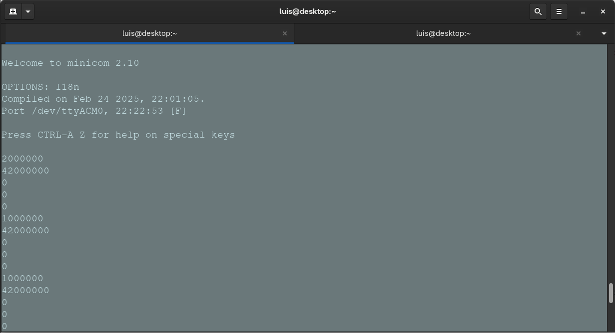
Well, now I have access to a data bus, now I’m actually reading a byte, let’s see what we get:
# Trust me, this is what minicom was printing, but I didn't take a screenshot,
# and I'm still not using version control so I don't want to revert anything I have.
# We'll see what's new on the C program shortly.
1000000
1000000
1000000
# etc...
That’s an interesting number. More interesting than 800000, that’s for sure.
Let’s write this number in binary:
0000 0001 0000 0000 0000 0000 0000 0000
Huh. Interesting… We’re waiting a 1, this is by no means a one… but, if we shift it 24 bits to the right… it is. So I told myself, I’m getting a 1, sort of. If I send data to the PS2 and if when shifting its responses 24 bits to the right we get the numbers we’re expecting… that would mean I’m now getting the right numbers from the PS2, So that’s what we’re going to do:
int main() {
// PIO configuration, etc. You know the drill.

  // We don't want to read weird values on the first loop.
  uint32_t data = 0xff;

  while (true) {
    //sleep_ms(1000);

    if ((data >> 24) == 0x01)
	  pio_sm_put_blocking(data_pio, data_sm, 0xff);

    if ((data >> 24) == 0x42)
      pio_sm_put_blocking(data_pio, data_sm, 0x41);

    if ((data >> 24) == 0x00)
      pio_sm_put_blocking(data_pio, data_sm, 0x5a);

    data = pio_sm_get_blocking(pio, sm);

    printf("%x\n", data);
  }
}
This is a rather crude pattern matching, I know. I got rid of the sleep directive to print more precise numbers to the console. Yes, they’re going to be printed really fast in succession, but they would be a more accurate representation of this loop. And it’s nothing that scrolling the terminal up can’t fix.
Those numbers seem pretty familiar. According to the Curious Inventor guide, this back and forth communication with the PS2 should look like this:
| Byte # | 1 | 2 | 3 | 4 | 5 |
|---|---|---|---|---|---|
| Command | 0x01 | 0x42 | 0x00 | 0x00 | 0x00 |
| Data | 0xff | 0x41 | 0x5a | 0xff | 0xff |
Actually, minus the last 2 data bytes which we’re not sending (we’re matching 0x00 with 0x5a) all of the command bytes are exactly these, when shifted 24 bits to the right, of course. This means that everything I read from the RX FIFO must be shifted 24 bits to the right, no biggie.
After all this, I’m pretty stoked. And this means that now comes the boring part: parsing all those bytes and sending appropriate responses. So exciting.