A while ago I bought a Hori RAP V3 SA, a neat little fight stick with a vewlix layout, all sanwa parts and a tray for the cable. It became my daily driver, but not without some modifications.
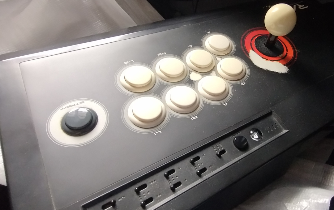
As you can see, its state was far from ideal. The tray’s door was also missing. So, for starters I had to remove the top plate’s decal and preferably replace it with a transparent acrylic plate to accommodate custom art and 3D print a new cable door.
Materials
For any build
- 24 multi core AWG wire.
- A universal crimping tool.
- 2.8mm female spade connectors
- (Optional) 2.5M hex spacers and compatible screws, to keep the PCB in place. Any height will do, but I recommend spacers measuring between 8 and 12mm.
For a Pico Fighting Board
- 4 and 5 pin 2.54mm JST female connectors.
For a universal GP2040 board
- An SSD1306 .96 inch OLED screen.
- Three 16mm push buttons: home, select and turbo.
- 2x3M nuts and bolts, with a length of at least 12mm.
- 4x2.5M nuts and bolts, with a length of at least 10mm.
For the USB cable
- For the simplest setup, a single micro USB (or USB C if your board uses that) cable will suffice.
- If you’re using a GP2040-CE board that exposes the USB connectors via 2.54 pins and you want to use the original cable, you’ll only need female DuPont connectors, their plastic housing and the pins to solder to the board, if it doesn’t have them already. An example of such a board is the GP2040-CE advanced breakout board.
- If you want to use the original cable but you’ll use a board that doesn’t expose its USB pins, I recommend using 4 pin GX16 connectors. You’ll need both male (for the cable that goes from the pico) and female (to connect the original cable to the pico’s micro USB cable). This listing sells a full set.
The cable door replacement
Easy. dwrkoa over on thingiverse has a replacement design ready to 3D print, so I just got in touch with a contact with a really good printer and got it that way. It was really cheap, too, like 5 bucks, and the quality is good. While it doesn’t have the finish of the rest of the case, looking at it from the front it’s hard to notice it’s 3D printed.
The acrylic plate
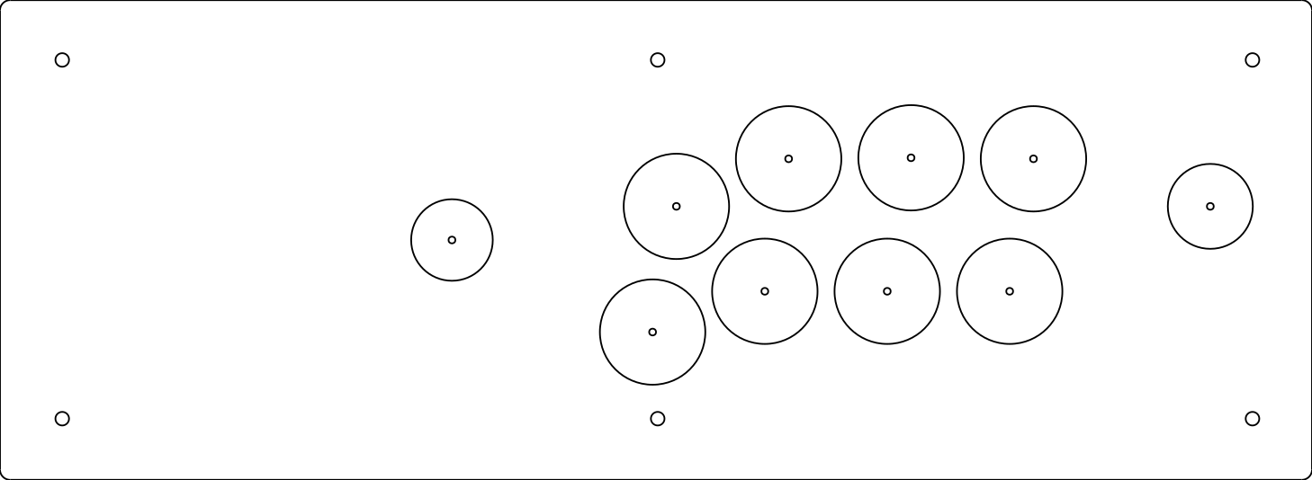
This is where things get interesting. Focus Attack does offer a replacement acrylic plate for this fight stick, but… 16 bucks plus whatever my PO box would charge me seemed a little excessive. So I decided to design it myself on LibreCAD and have it cut by a local shop. All in all, it cost me like 10 bucks. You can download the DXF to do this yourself here, it will also be permanently linked in the goodies section.
For art, you can download FocusAttack’s photoshop template for editing it, as they are largely compatible. You can also download the SVG I exported from LibreCAD, again, on the goodies section. The SVG has the button and joystick hole centers marked, so you can cut with confidence with a tool like this.
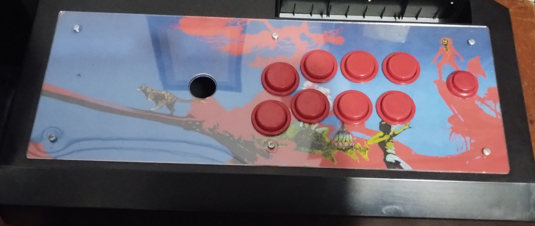
The result’s pretty good!
The GP2040-CE board
GP2040-CE is an RP2040 powered open source firmware for arcade controllers. It sports the best latency on the market for PC, even exceeding Brook boards, which were, for a long time, the only game in town.
I have been following the project for years, even before the community edition, when FeralAI started the project, and so, it’s my firmware of choice for custom controllers. All of my fightsticks have a board with it inside. This one wasn’t going to be the exception.
So, two paths present themselves here. As you can see, the original auxiliary panel has a lot of dials we don’t have a use for: we only need the home and select buttons and perhaps a single dial for turbo functionality. The original board uses a slider-per-button turbo configuration, while GP2040-CE uses a turbo button (you press the button you want to be in turbo mode and then press the turbo button).
It has also player LEDs, which not all GP2040 boards accommodate, but the firmware is compatible with them. You can actually use FeralAI’s original pico fighting board to expose the pins to wire the LEDs, but, you’ll need to order the pcb from a manufacturer like JLCPCB and solder the 4 tiny resistors for the LEDs, so, not for the faint of heart, but an option nonetheless.
The GP2040 board that retailers usually sell purportedly supports player indicator LEDs, but at plain sight I’m not sure how you would go on to wire them, as I can’t see any terminals that indicate they’re the player LEDs’, at least not in the same way the pico fighting board does.
What it does have going for it that the pico fighting board does not is it exposes the USB pins via a 5 pin 2.54mm terminal, so you can just use the original cable, which I recommend because it’s really well made and quite long. You do have to change its JST connectors to DuPont male connectors though, but more on that later.
As you can see, this is not precisely a simple mod. You have to both solder and crimp cables — it’s not particularly hard, but it requires tools you may not have. I have a solution for this… but first, let’s assume you want to use the original panel (and its PCB)
Adapting the panel for the GP2040 board
The original panel’s PCB exposes the turbo dials, the LEDs, the home and select buttons and the joystick mode via two 1.5mm (I believe, but this is not relevant, we’ll change them anyway) JST cables.
Using a Pico Fighting Board
If you go the pico fighting board route, you’ll have to change the JST connectors from the original 1.5mm to 2.54mm female connectors (we’ll need both 4 pin and 5 pin connectors) You do this by pushing the cables out of their housing, using a thin screwdriver to bend the plastic locks keeping the cables in, like this. That video does it with some DuPont cables but the process is the same. If you break the plastic locks, don’t worry, we want only the cables.
Once you have the bare cables, you just slide them in their new housing, following both the order and grouping the Pico Fighting board expects: see the image. The player LEDs’ connector has: voltage and players 1 to 4. So, you grab the cables that are soldered to the panel PCB’s led terminals and slide them in their new connector housing in that order.
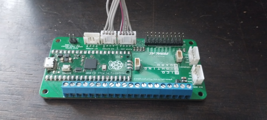
For turbo, you can use any of the slider’s cables, I recommend using the DP-LS-RS switcher just for convenience. Do be wary that, because it’s a slider and not a button, the turbo functionality will be a little wonky: you’ll press your button, then slide the switcher all the way to the right, then release any buttons, including the one you enabled turbo on, and then move the switcher back to the left.
So, you’ll end up with two cables: a 5-pin one for the LEDs and a fourth one that I recommend you use with the panel’s select, home and DP-LS-RS switcher and its ground signal. You’ll use the web configurator to map these pins correctly, as the JST connectors on the pico fighting board refer to either 4 optional buttons (GPIO pins not mapped to anything) or the connector for the DP-RS-LS switcher itself, but whose pins we can use for arbitrary buttons.
Using anything else
Well, let’s say you’ll use… anything else, be that the advanced breakout board, a bare pico (yes, you can do that too. And it’s the cheaper option), a bare pico in a brook form factor, using TheTrain’s basic breakout board, you name it.
The problem here, besides all the useless turbo switchers, are the LEDs. Unless you solder some resistors on a plate or something equally esoteric and ugly, you won’t be using them. You’re left with a panel that’s 80% useless.
Enter… a replacement panel design, ready to 3D print, made by yours truly:
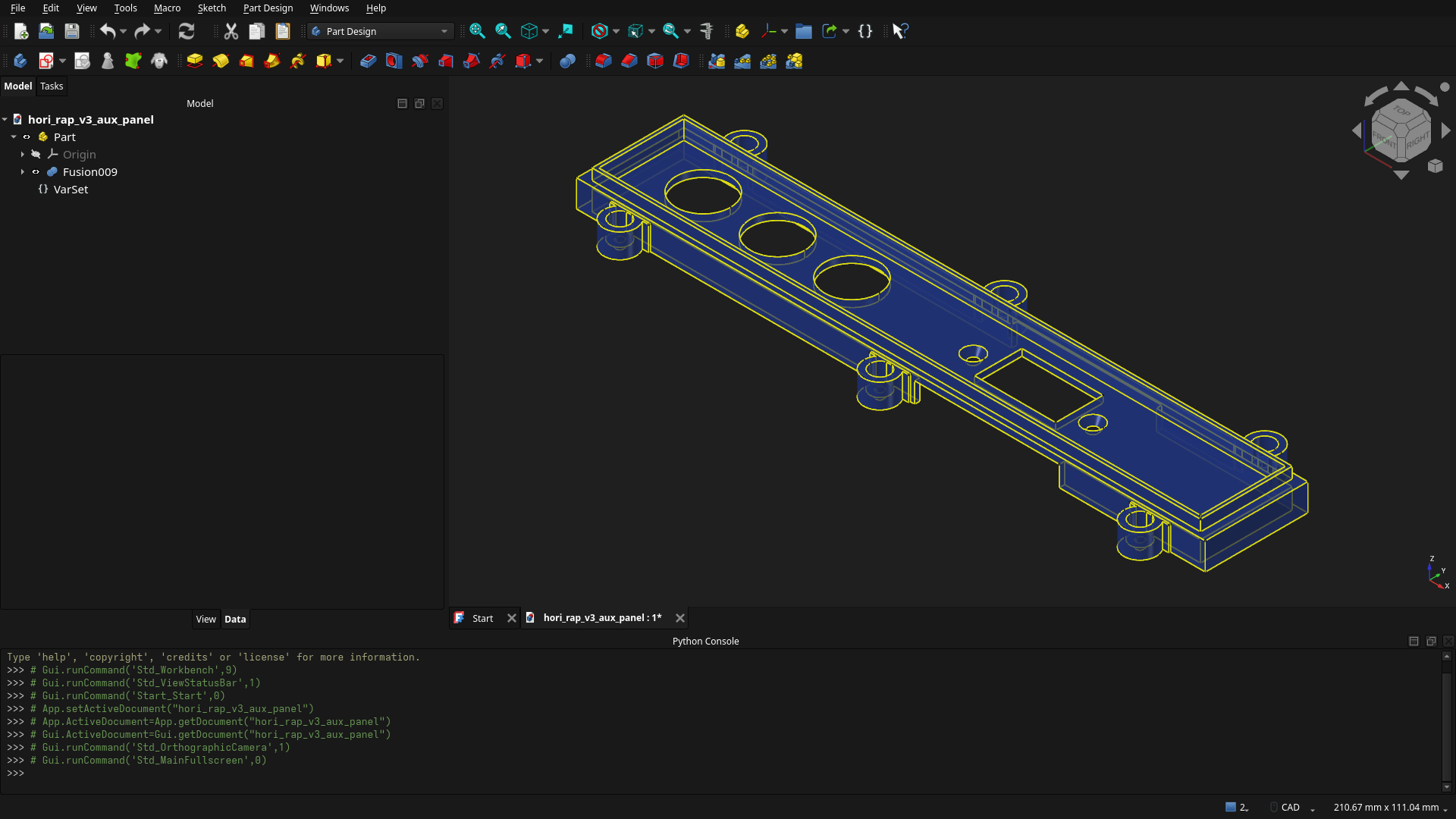
This is a bespoke panel design for GP2040-CE: it sports three holes for the home, select and turbo buttons, compatible with 16mm buttons and a display window for .96 inch oled screens, which GP2040-CE is famously compatible with, and shows even more useful data than just the player number: it shows the input mode, the layout, button presses, which buttons have turbo enabled, the input history, and more. Also, it shows if you’re using macros and that can’t be disabled, so everyone at your local venue can see that you’re a shameless cheater. And you can customize it with splash screens.
Download it, print both the panel and the OLED screen adapter, screw the display to the adapter, on the side of the tall walls, and then screw the adapter to the panel. Easy.
Materials: 4xM2.5 flathead screws of a minimum length of 10mm and 2 M3 flathead screws of minimum 12mm. And nuts for both measurements.
Slide the buttons in, screw them, and you’re on. You can install the panel as you will with the original, original screws and all.
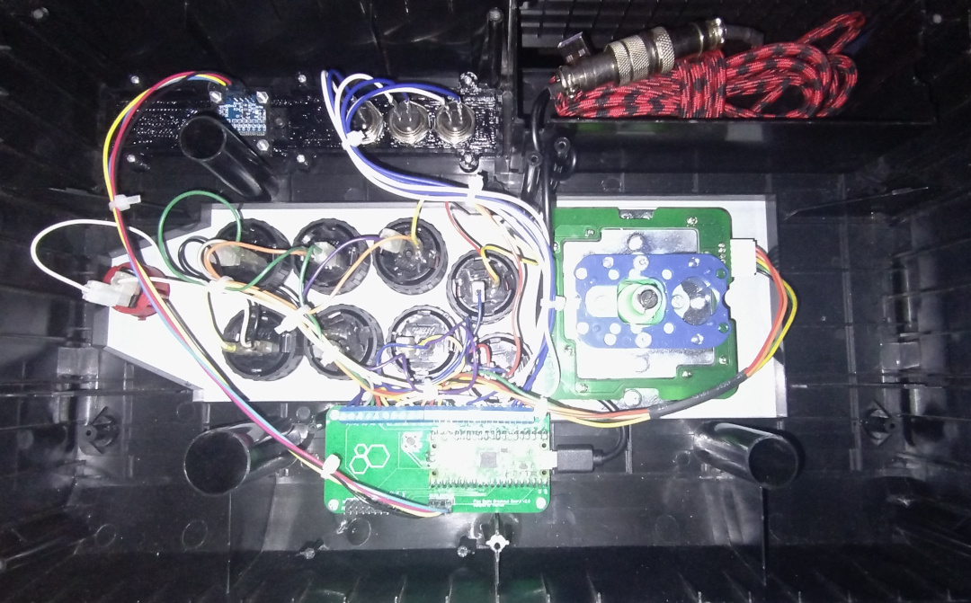
With the buttons and display in place you can go ahead and wire them to your board however you see fit. In the pic below you can see the internals of my fight stick:
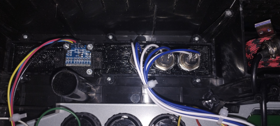
And a close-up of the panel’s bottom:
The USB cable
You have two options: either use a new cable, connecting it directly via micro USB (if you’re using a bare pico or a PCB that exposes a bare pico) or USB-C (if you’re using an advanced breakout board) or adapt the original to the USB connector of your board.
The first is the easy one. The second one does require soldering.
As you can see in the picture above, I’m using GX16 aviator connectors to join the micro USB cable that connects with the pico and the cable. I’m not using the original however, as I wanted a cable that I could cover with paracord and the original is too thick. But I still do recommend you use the original.
Buy a 4 pin, male-female set with docking, like this one.
Soldering them is easy, both connectors mark their pin numbers, so 1 on the male end goes with 1 in the female end. Which cable you solder in which pin largely depends on what cable you soldered first. Let me explain.
A standard USB cable is color-coded. If you cut and peel it, you will then come across 4 wires, each of a particular color. This is standard: the black is the ground, red is the power input, green D+ and white D-. You don’t have to peel and cut your controller’s cable though. Just cut the connector to reveal the wires and have them ready to be soldered. You’ll do the same with the cable that goes to your pico: cut the USB A connector (not the one that goes to the pico) and peel each wire.
The original cable also uses two ground wires, you can solder them together. Then, you can decide which pin in the aviator connector goes with which wire. Try to use a layout that makes soldering comfortable — separate each wire carefully and arrange them in the connector.
Once you’ve soldered each wire to the connector, envelope it with insulator tape and slide the housing back in.
This is an example of the process, in spanish, and in an even stricter configuration as it needs to be compatible with the Madcatz TE’s USB pinout. You can also search for any videos of custom cable building from mechanical keyboard enthusiasts. Yes, it’s literally the same process.
If you’re using an advanced breakout board, the process is simpler: cut the cable, crimp them with female DuPont connectors and slide each inside a DuPont plastic housing. You can just then connect each wire directly to the 2.54 terminals exposed to your PCB. No soldering necessary, for the cable at least (you still have to solder the terminal to the USB pins in your board, but this is a way far simpler process) but you do need a crimping tool and 5 DuPont connectors.
Installing a Seimitsu LS32
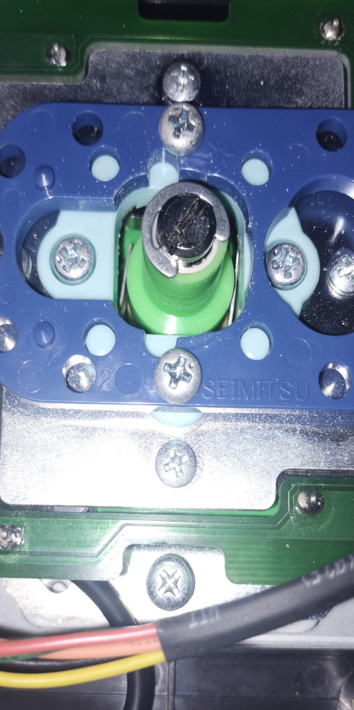
I also went ahead and switched the original sanwa stick for a seimitsu LS32. What makes this joystick not get along with this particular controller is its shaft height, thus, you need an SS mounting plate… a plate that doesn’t get along with the panel either.
So, to screw it, you’ll use only the top and bottom holes in the middle, not the holes in the corners as those do not align. But I noticed the screw didn’t go all the way, so I used a couple of M4 nuts so I could screw the bolt down. The nuts function as spacers more or less.
Installing the buttons
The original PCB used a 2-pin JST connector for each button, each pair being the ground and signal.
The GP2040-CE I’m using, and most of them, anyway, instead expose a pin for each button and just 3 or 4 pins for ground. This means, we need to wire them in a daisy chain configuration to connect the buttons to ground.
While you can buy daisy chain cables on aliexpress, for this project you probably already bought a crimping tool. While you don’t need to buy new connectors for the signal wires, you’ll need them to crimp each cable on daisy chain.
You can reuse the original cables. Snip them from their plastic housing and peel the ends. Grab half of them, they’ll be your signal wires. Cut the connectors of the other half, you’ll build your ground cable with them: you’ll need 2.8mm spade connectors. It’s kinda tricky to crimp two cables at once, so if you get it wrong don’t be afraid to either cut the cable or remove the botched spade and try again.
Daisy chaining
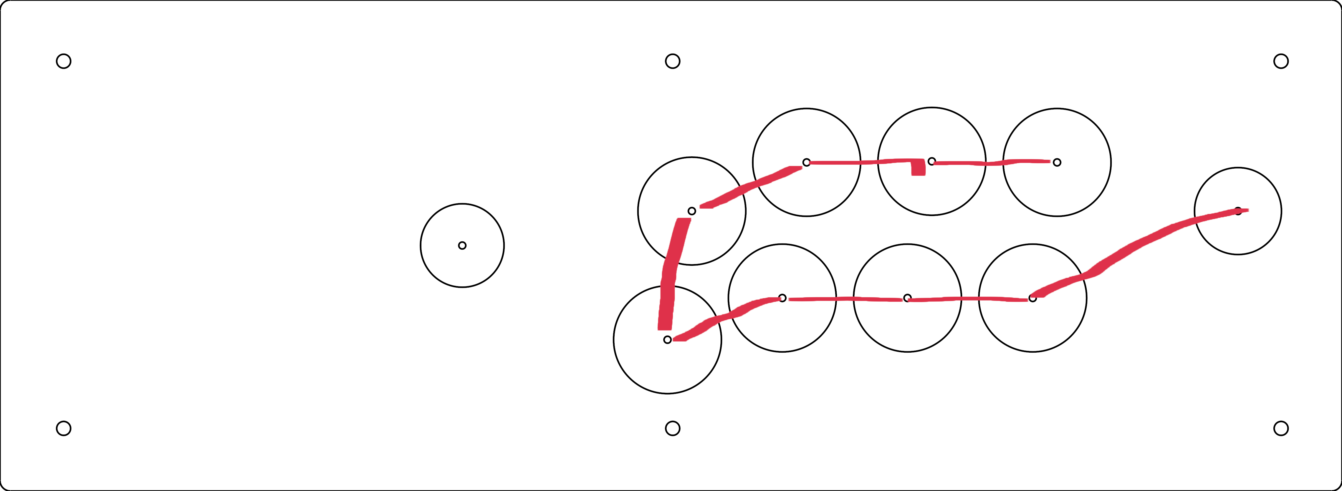
The idea here is to start at one extreme of the button layout and wire each subsequent button, finishing with a peeled wire. The first wire will have a single spade, its other side will be the second step of the connection, with two wires in, so on and so forth.
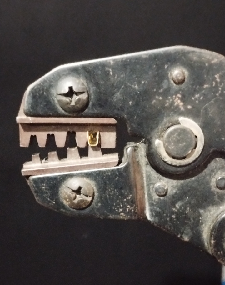
To crimp your cable, put the spade connector in the furthermost crimping hole of your tool.
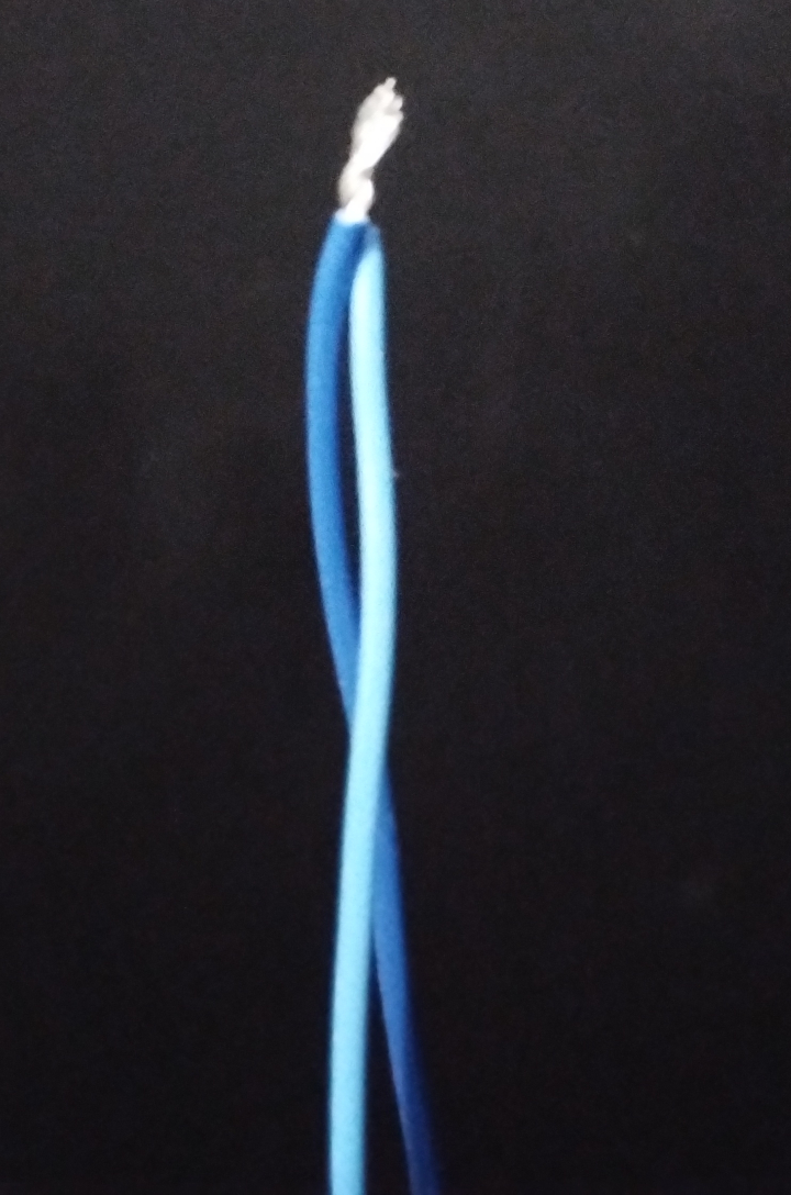
Peel and entwine each wire and slide your plastic cover if you’ll use them. To cover them you can also use heat shrink tubing, just like the original cables do.
Slide the cable in the spade and crimp them real good, but only crimp the second set of legs, don’t bother with the first, as the two joined cables are too thick for the crimping tool, instead, use regular pliers to bend them in place.
Do the same with the wire’s other end and until you have 9 connectors (start + the 8 face buttons) in your daisy chain cable. The last wire you’ll crimp should have its other end peeled — That wire will go in one of the pico’s ground terminal. Follow the diagram for an example daisy chain wiring:
Results
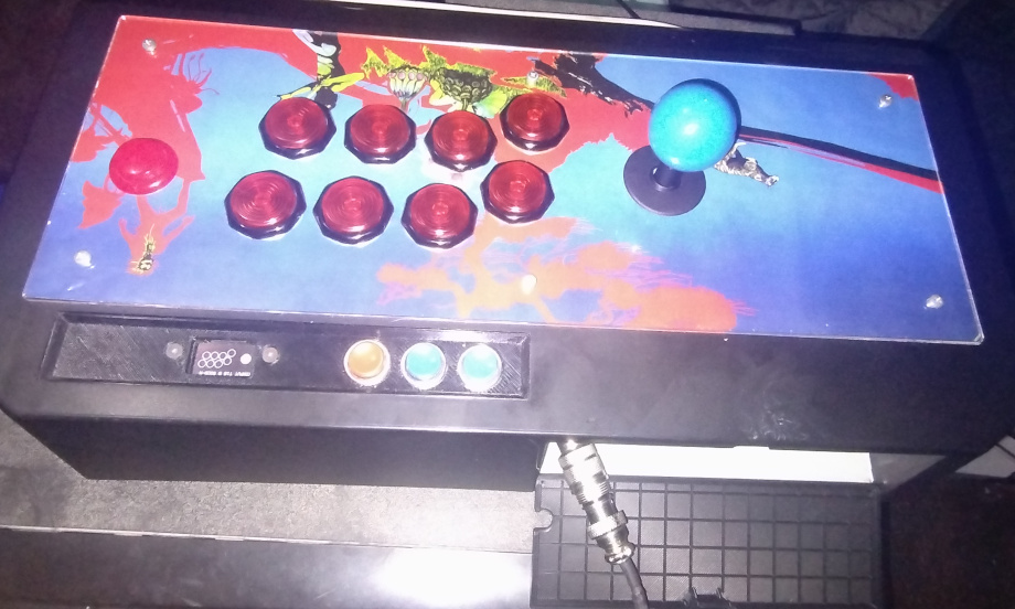
After installing the panel, the acrylic plate and the seimitsu stick I also decided to change the buttons for some gamer fingers, clicky blue, of course.
This is how it looks:
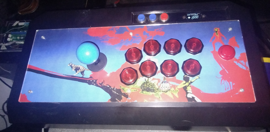
Roger Dean’s art looking real good on an arcade stick:
Goodies
- The panel design. Besides the STL files for printing I also included the freecad project files.
- The layout for laser cutting.
- The layout in SVG format. Make sure to import it to your favorite photo editing software with the correct measurements.